I am continuing on the Carbon3D related articles in an attempt to “solve” what it is they are both talking about and trying to solve. There is also a few other topics I want to cover. Carbon3D is essentially talking about a surface technology that prohibits the cured resin to stick, essentially a non-stick surface like Teflon on a frying pan. With that in mind, it is quite clear that cured resin adhere to the VAT surface and that this must be solved, so let’s look at that first.
Here is their webpage
http://carbon3d.com/Key points from the articles.
• Between 25 and 100 times faster than what’s available on the market today.
• Continuous Liquid Interface Production technology (CLIP)
• Works by harnessing the power of light and oxygen to cure a photosensitive resin.
• SLA based.
• Use light as a way to cure the resin, and oxygen as an inhibiting agent.
• By bringing oxygen into the equation, a traditionally mechanical technique for 3D printing suddenly becomes a tuneable photochemical process which rapidly decreases production times.
• Removes the layering effect.
• The CLIP process relies on a special transparent and permeable window which allows both light and oxygen to get through.
• The machine then is able to control the exact amount of oxygen and when that oxygen is permitted into the resin pool. The oxygen thus acts to inhibit the resin from curing in certain areas as the light cures those areas not exposed to the oxygen.
• Thus the oxygen is able to create a ‘dead zone’ (layer).
• Small as tens of microns thick.
One micron (1 µm) is 0.001 mm, so 1/10’th of that would equal 0.0001 which is extremely thin. The article then mentions: about the diameter of 2-3 red blood cells. A typical human erythrocyte (red blood cell) has a disk diameter of approximately 6.2–8.2 µm. So if you take the 2-3 blood cell’s diameter you end up with 12.4 µm to 24.6 µm which certainly not is 1/10’th of a micron but rather 1-2/10 of a mm which seems to be more correct.• Unlike conventional 3D printing, their printer continuously forms a new object, rather than printing it in layers.
• Tweak designs by making changes to software, rather than building new manufacturing machines
• The resin solidifies when ultraviolet light hits it (a process called photopolymerization). So to create the desired item, a projector underneath the resin pool shoots UV light, in the form of a series of cross-sectional images of the object. Light, in a sense, is the blade that the printer uses to sculpt its products. Meanwhile, oxygen prevents this reaction from occurring — so to stop the object from simply hardening and sticking to the floor of the pool, there's a layer of dissolved oxygen there, creating an ultra-thin "dead zone" at the very bottom.
• With the projector and platform in sync, the object forms as it moves upward, with new resin continuously solidifying just above the dead zone.
• The new method is much faster because it works continually, instead of in layers, eliminating this step.
• The lack of layers also makes the products of this new method stronger. That's because they're solid objects, rather than layers of material stacked together.
This is a fairly big topic and I’m guessing, a concern among people building and using 3D printers. For one, I’d like to start with the elephant in the room which is the production time and the result, aka surface and strength of the object.
Layers, build time and how too is something I’ve been thinking about for a long time without really looking at the practicality of it all, but will give it an attempt now.
Let’s start with the basic.
Source;
http://en.wikipedia.org/wiki/Stereolith ... TechnologyStereolithography is an additive manufacturing process which employs a vat of liquid ultraviolet curable photopolymer "resin" and an ultraviolet laser to build parts' layers one at a time. For each layer, the laser beam traces a cross-section of the part pattern on the surface of the liquid resin. Exposure to the ultraviolet laser light cures and solidifies the pattern traced on the resin and joins it to the layer below.
After the pattern has been traced, the SLA's elevator platform descends by a distance equal to the thickness of a single layer, typically 0.05 mm to 0.15 mm (0.002" to 0.006"). Then, a resin-filled blade sweeps across the cross section of the part, re-coating it with fresh material. On this new liquid surface, the subsequent layer pattern is traced, joining the previous layer. A complete 3-D part is formed by this process. After being built, parts are immersed in a chemical bath in order to be cleaned of excess resin and are subsequently cured in an ultraviolet oven.
- end –
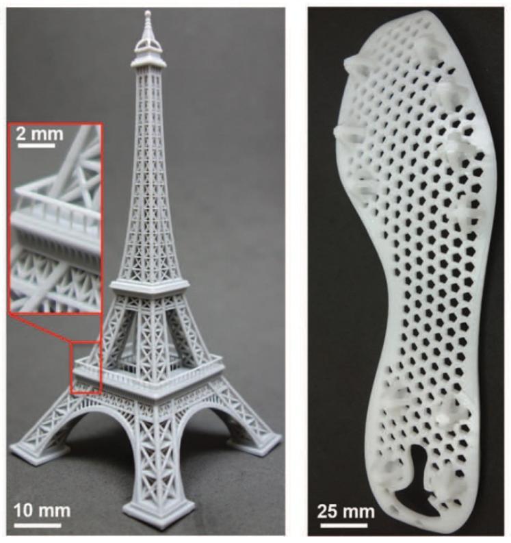
Laser sintering (SLS) which is a cousin of the SLA use the laser point stimulation to cure the resin, it creates vector points in a 3 dimensional space by adding energy (photon packages) to the photopolymer which reacts and creates molecular bonds and hardens. The disadvantage of this is that you get many clusters that clump together and appears as a solid object when looking at it. The surface area will also due to this become highly textured. Similar to what you can see in the picture.
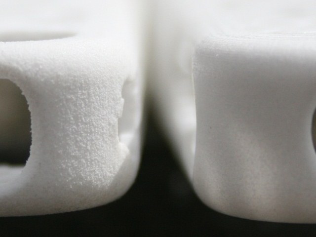
Left is raw item while the one on the right has been sandblasted to polish the surface info: Shapeways. Shapeways use several types of technology's where one is the Polyjet version. Formlab Form1+ use the laser based type of SLA.

You can clearly see the texture and voxel based surface in this picture and its a rather big issue. They create vector clusters in the order of 300 µm (0.3 mm / 0.0118 ") on the X & Y axis while the Z axis (layer axis) is in the order of 25 - 200 µm. It is possible to see 100 µm with the naked eye and sometimes depending on the light etc, between 50-100 µm is not that big of a challenge, but under 50 µm starts to become more difficult if not impossible for most people.
"Experts believe that the naked eye — a normal eye with regular vision and unaided by any other tools — can see objects as small as about 0.1 millimeters. To put this in perspective, the tiniest things a human being can usually see with the naked eye are things like human hair (with the naked eye and under a microscope) and lice (with the naked eye and under a microscope)." - See more at:
http://wonderopolis.org/wonder/what-is- ... Rt2d1.dpufSo lets use an average here and say 75 µm which is in the middle of 50 and 100 µm. To get some perspective on microns and how it impacts the surface of our items, lets re post one photo from the article earlier.
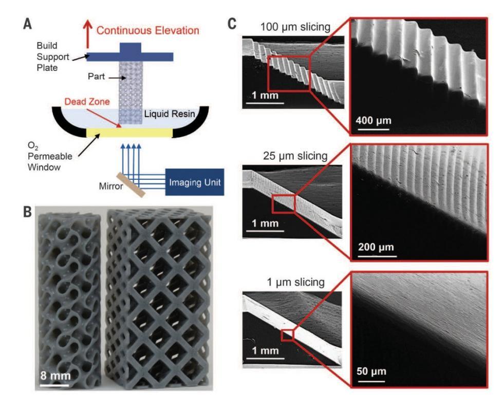
First of all, the pictures under row C is under a microscope. I have a micrometer that I use to evaluate the microns mentioned here. 25 µm distance is not that difficult to see. Lets go down to 12.5 µm which is half and I'll admit that it is getting close to the limit of what my eye can detect at an arms length. So lets use a round number and say 10 µm and that is my personal limit.
Keep these two numbers in mind, (25 and 10) they are important in relationship to what we can do on the Z axis because there are limitations but also ways to get around them in the software which I will get back to.
Now, lets start with one "fixed" issue that is out starting point regarding layer growth and remember, I do not have any inside info on tricks or solutions Carbon3D utilises here so I am only going to use my own form for speculation and collected data to get to the conclusion you are about to read. So what is our first limitation ? well, that has to be the photopolymer.
"The exposure time, % of photo initiator and % of photo inhibitor all work together to create the layer thickness. With a 2700 lumen DLP projector this resin will cure a 0.1mm thick layer in 2 to 4 seconds."
3dinkThis is the starting point for my speculation.
0.1 mm = 100 µm, so lets use the higher number of 4 sec. 4 sec = 4000 ms. So: distance over time = 100 µm / 4000 ms = 0.025 µm/ms. a 2 sec curing time = 0.0125 µm Can we get down to that stepper motor resolution ?
Indeed we can. Curing at a layer thickness of 0.025 µm is not an issue. In clear text: We can create a 0.025 µm layer during 1 ms. So by simply looking at what motor resolution we can get and how long X distance (0.025 µm) on the Z axis takes for the photopolymer to cure said layer thickness, to create a situation where you have a continues motion or very close to a continues motion should not be a problem. We can even afford to have a few ms break between the images. Do note here that there is another element that I have not encountered for and that is the energy in the equation. So we do have that to consider at a later time. But lets assume right here and now that we do have required energy, we know exactly how much is needed and we have a stepper motor and gearbox situation that allow us to have a very thin layer, ridiculous thin... lol
As long as the photopolymer properly cures which is related to energy and time, to seamless continue to the next layer should not be that difficult. Remember that the layer surface is not a dead stop for the light, it will affect the already cured area and on a distance, so the curing will continue for lets say half the energy as originally were needed but this energy amount might well be above the minimum requiered. And yes it will to some degree affect the photopolymer under/over the resin build surface.
If the software allows it: a slice of 0.025 µm is not a problem. It is a software and not a physical machine. There should not be any restrictions on how many slices you can generate and if there are, one should address that. The other thing which is related to speed is the energy. Lets play with the number 1 watt. 1 W is the required energy to cure all the molecular bonds on each molecular level. If you increase this to 2 W, you are increasing the speed as well. Now ofc, there are limitations to reaction times and there is always an upper speed limit, but I do not think we to look at that atm, and besides, such fine calculations is nothing I can deal with atm.
So, we can generally find the curing time and we can find the energy required (comes together with chemical datasheet) and we can find and control the resolution on the Z axis. So with all of this sort of in place, why are people dealing with 100-300 µm layers or more ? I am not saying that 0.025 µm is practical, lets jump to 1 µm as a practical number or even 15 µm. 15 µm seams like Mount Everest .. LOL, but I am rather confident that all of this can be solved.
So continues growth or seemingly continues is perhaps not as solid as we think by reading the article. I have speculated and even done some simple math to show what is involved for each layer, so if each layer even under a microscope seam to be seamless and continues, is that then not a trick ?
However, there is a real thing if we look at layer bonding. That if each layer is bonded with one another where the molecules are allowed to "grab" or stick together in a chemical bond rather than via surface tension between the layers, then certainly the object will become stronger over all. So there is something to continues growth beyond the visual appearance to the customer.
***
So that is me looking at the growth. Now for the other topic which is: The problem of the cured resin to stick to the VAT surface (?). We know that the growth happen in 4 dimensions. We can manipulate or influence all 4 besides the pixel segments on the Y & X axis which so far is limited to around 156 µm or (0.15 mm). But few items will have a footprint smaller than this and one need a material that will support such thin structures. That limit is often 300 µm (0.3 mm) so 156 µm on the Y & X axis might not be an issue at all. Regarding the growth on the Z axis, if you know the speed of solid layers creation and you control the Z axis speed and these are calibrated, then you surely must be capable of moving the Z axis or build surface in such a way that the build surface remains more or less stationary in 3D space.
Look at it this way: We control the growth, we know when and why. If everything is calibrated and working at its optimum, then
would create a situation were the objects surface builds all the way to the VAT surface ? am I missing something ????
As far as I know, oxygen is
not a part of the molecular bond creation, light is - see picture.
Reichmanis, Elsa; Crivello, James (2014). "Photopolymer Materials and Processes for Advanced Technologies". Chem. Mater. 26: 533–548.
So if oxygen is not part of the chemical reaction - added oxygen that is - then the text is a bit misleading. You can certainly not introduce oxygen in the photopolymer outside the desired curing are, there is no way to control such things, and if you expand the curing area to the previous oxygen saturated polymer you would need to remove it and such an approach is simply not feasible. So the oxygen layer must be a way to prevent the solidified material to stick or adhere to the VAT surface. You can certainly not use pressurised air under the photopolymer, that would create microscopic air pockets inside the photopolymer as it cures and over all weaken the structure. Glass is a solid and not oxygen or air permeable. However, there are plastics, known as Mylar (
Biaxially-oriented polyethylene terephthalate) that is O2 permeable. You can certainly not introduce oxygen in the photopolymer outside the desired curing are, there is no way to control such things.
And you need photopolymer under the object since that is the place where you take material from to build a new one.
- What Gas Permeable Contact Lenses Are Made OfGas permeable contacts, also called GP or RGP lenses, are rigid (hard) contact lenses. Like hydrogels used for soft lenses, materials used to create GP contact lenses also are "gas permeable," allowing oxygen to pass through the lenses to the cornea. Unlike soft lenses, however, rigid gas permeable lenses do not contain significant amounts of water. Instead, GP lenses rely on their microscopically porous nature to transmit oxygen to the cornea. Prior to the development of GP lenses in the 1970s, conventional hard contact lenses were made of a hard plastic material called polymethyl methacrylate (PMMA). Though PMMA has excellent optical qualities, durability and biocompatibility, it has no oxygen permeability, and many people could not tolerate or safely wear PMMA hard contact lenses for this reason. Gas permeable contact lens materials generally are classified according to their "Dk" value, which is a measure of their oxygen permeability. Materials with a high Dk transmit more oxygen to the eye than those with a low Dk value:
Low Dk is < 12
Medium Dk is 15-30
High Dk is 31-60
Super Dk is 61-100
Hyper Dk is > 100
The first modern GP lenses to gain wide acceptance were made of an oxygen permeable material called silicone acrylate (SA). These lenses were introduced in the late 1970s under the brand name Polycon and had a Dk value of 12. Since then, new gas permeable lens materials have been developed that provide greater oxygen transmissibility, enabling even overnight wear of GP contacts.
And here is such a sealing film or layer wich Carbon3D talks about:
http://www.thomassci.com/Supplies/Plate ... 0Permeable
- Gas permeable
- Clear mylar
- Adhesive-backed film
--------------------------
You need a solid transparent surface, glass or plastic. They are using the SLA-DLP principle. CLIP does not eliminate what goes into SLA printing. You then have the Mylar gas permeable film followed by the photopolymer ontop of that just like we saw in one of the illustrations. So perhaps Carbon3D has found a good solution to prevent the object to stick to the VAT surface, but they have certainly not changed the chemistry. I explained how the growth surface can be maintained and fixed at a specific hight from the VAT surface, does that then eliminate Carbon3D's technique ? Ww shall see, in due time.
************************
Some of the information is borrowed from another debate over at b9creator.com/forum.
hoytyeatman@yahoo.comHi There:
I now understand how Mike says the PDMS inhibits the cure via a permeable surface to oxygen. Mike's quote is below.
"PDMS inhibits cure because it permeable to oxygen. Oxygen diffuses from the atmosphere into the PDMS material. The oxygen present on the surface of the PDMS inhibits cure of the resin in contact with the surface. That leaves a microscopic lubricating layer of uncured resin. Any substance that is optically clear and oxygen permeable should work, but I've not found any others, yet."
I am having some laser cut Acrylic VAT parts made and will be using a "Water White Glass Plate" Window 4" x 5.13" instead of Acrylic for better cleaning without the micro scratches.
http://www.waterwhiteglass.com/ I am also looking for an Adhesive film that is gas permeable that might work as the release instead of PDMS. Possible example:
http://www.thomassci.com/Supplies/Plate ... 0Permeable I believe there must be some Adhesive films out there that can replicate what the PDMS is doing to inhibit the cure of the resin at the contact point. Any thoughts or leads on materials to test would be appreciated.
Best,
Hoyt
"Welcome to Water White Glass More Information
Water white, low iron, ultra clear glass transmits 98% to 99% of light, and is anti-glare and ant-reflective coated. This glass is becoming very important to the movie theater industry, as the industry turns to digital equipment. Used as a theater glass, our water white glass outperforms other ultra clear products. We use a process that insures defect free glass. Other typical uses of water white glass are in display cases and photo booths. Thicknesses are available in 3mm, 6mm and 10mm. Water White Glass under 3mm thick transmits 99% of visible light, while over 3mm thick transmits 98% of visible light. Sizes are available up to 6' X 8'. Use our contact form to request a quote. Please include size and thickness specifications.
Water white clear glass (98% transmission) has a variety of other potential uses. One use for this clear glass is for displaying graphics and art on the glass. Water white clear glass can be used for the application of silk-screen images. The glass is so clear and anti-reflective that it is transparent to the image. From a short distance the graphics or art appears to float. Water white glass is available as tempered product. Hydrophobic coating is also available to repel dust, dirt, water and oil build-up"*************************************
Lead free glass by the way will give you the same or similar clear low distortion we probably need.
"Starfire Clear Glass is a lead free, low iron product that represents the very best in making glass trophies, although not clear enough to be called "crystal". Aslight blue tint is evident in the mostly-clear products.
A kind of super-clear low iron glass; also called low-iron glass and high-transparent glass; a sort of high-quality, multi-functional new up-market glass with light transmittance of 91% or more; featured by crystal clear, nobleness and elegance; known as "Crystal Prince" in the glass family. G-Crystal ultra-clear glass shows extraordinary talents in the building field for its crystal-like high quality, performing greatly in energy conservation and environmental protection, lighting buildings with fashionable avant-garde architectural styles and design concepts, and motivate designer's creativity and inspiration to fully unfold the high grade and fashion sense of modern architecture."
There we go, clear as lead free glass ... lol
The b9creator debate raises something that is both of interest to me personally and useful:
Question; How do the other DLP printers get around the PMDS layer? Just wondering?
Answer; There are some DLP 3d printers that print from bottom up, meaning the projector is on the top shining down on a bath of resin and curing one layer at a time while the build platform is slowly lowered. Those don't need any PDMS, just lots of resin[/b].
- See the whole debate;
http://b9creator.com/forum/viewtopic.php?t=890


To see this in action, search EnvisionTEC Ultra on Youtube. Here is a demonstration;
https://www.youtube.com/watch?v=a1louDxSNpYhttps://www.youtube.com/watch?v=JjFYWzbg0hoIf you find flaws in my analyse, do mention it. This is for now only on a theoretical level. - So with that being said, lets move on.
/cdn0.vox-cdn.com/uploads/chorus_asset/file/3508660/3d_printing_gif.0.gif)